Everardo Shain Ruvalcaba
Wednesday, May 11, 2022
Upright CNC Router
Overview
This team project included the CAD modeling of a motor driven Upright CNC Router with polar axes, and its control with PD and PID controllers using MATLAB and Simulink. We designed a HMI with a mode selector menu (1 coordinate, circle, rectangle, triangle and 3 coordinates), and plotted each comparison between reference and control signals, plus an additional plot with the error signal. The most complex tasks were the signal generation for each shape by applying horizontal and vertical forces, and an additional conversion to those signals as our robot moved within polar axes. The PD and PID tuning was made by making several trial and error experiments on each mode until the stationary error was almost zero.
Tools
- Simulink: importing CAD model, simultion, HMI design and main programming logic with block diagrams.
- MATLAB: integration with Simulink, plots coding.
- SolidWorks: CAD modeling.
Process
Assembly
- Designed the router model with SolidWorks.
- Imported the CAD model with Simscape Multibody Link plugin.
- Added two control signals at each joint, representing vertical and horizontal linear forces (X and Y axes).
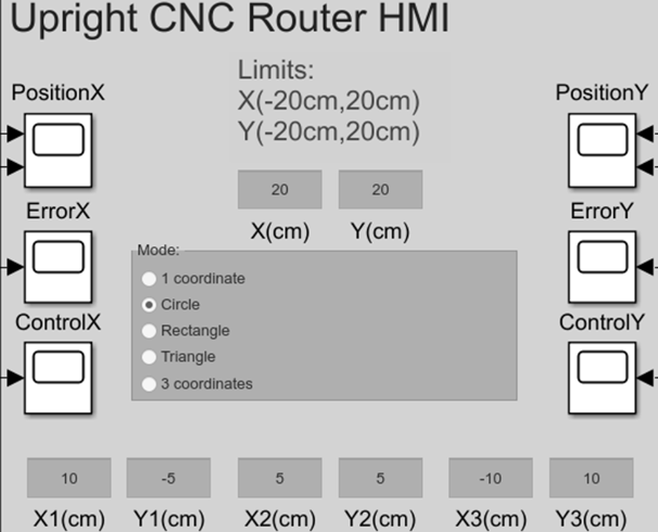
HMI
- Added a mode selector menu (1 coordinate, circle, rectangle, triangle and 3 coordinates).
- Included input blocks for desired coordinates.
- Plotted each control signal with its corresponding reference and error. Plain MATLAB code was used for the plots instead of block diagrams.
Mode Selector
- Linked the mode selector menu variable to individual case blocks.
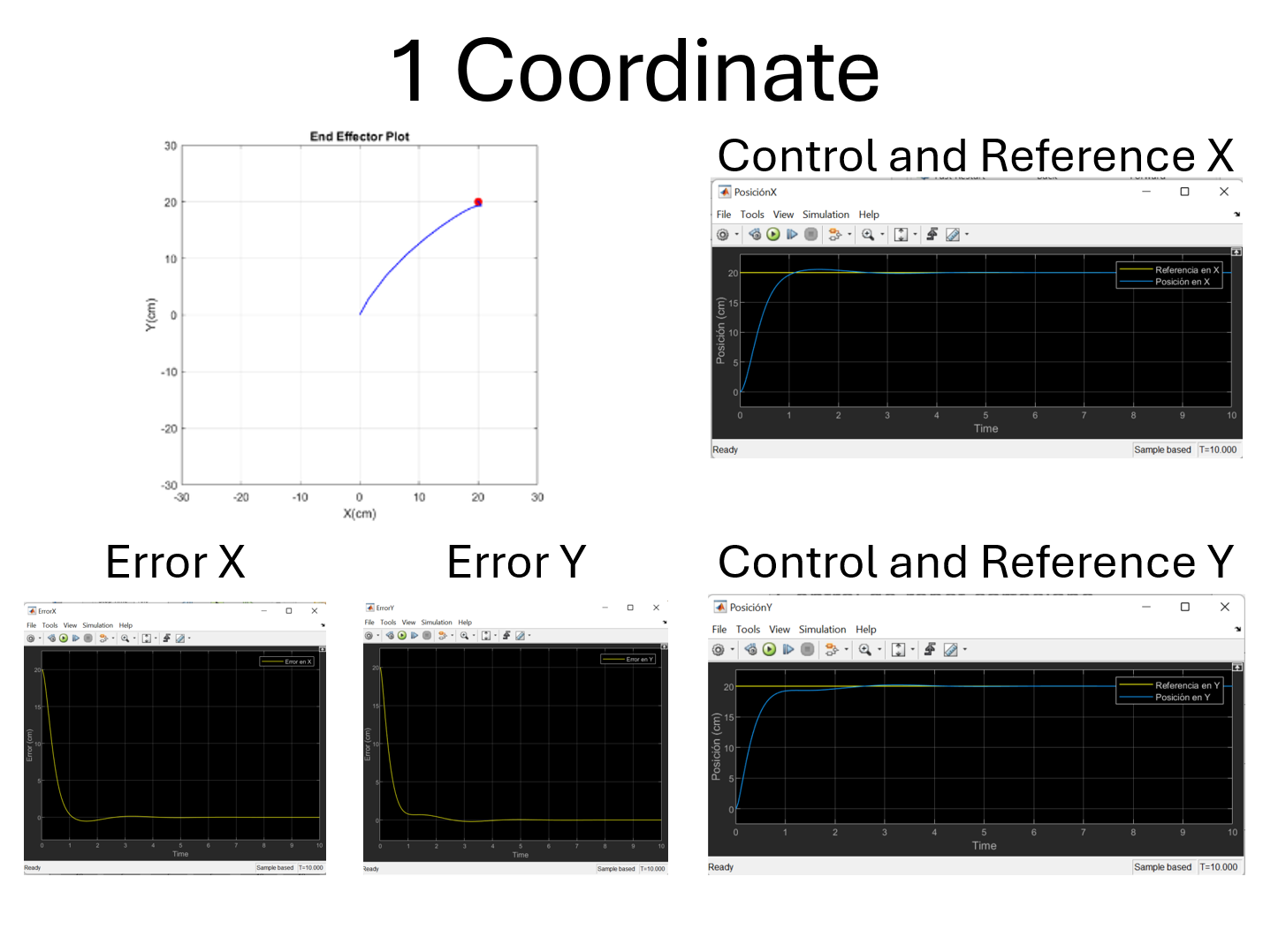
1 Coordinate
- Generated a constant 10 s reference signal to reach user-defined coordinate:
- X reference: input from the first element of the first coordinate from HMI.
- Y reference: input from the second element of the first coordinate from HMI.
- Designed a PD controller with reference, feedback and output signals. Parameters: $Kp=8$, $Kd=3$.
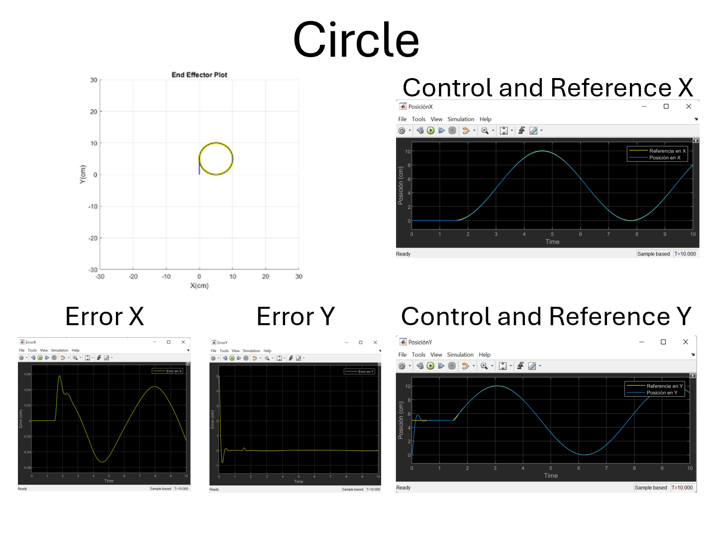
Circle
- Generated a 10 s reference signal with block elements to draw a 5 cm radius circle starting at (0 cm, 5 cm).
- X reference: initial 1.5 s Heaviside step function to reach initial X coordinate (0 cm). Trigonometric function $-5cos(t-1.5)+5$ to make the circle after the first 1.5 s.
- Y reference: initial 1.5 s Heaviside step function to reach initial Y coordinate (5 cm). Trigonometric function $5sin(t-1.5)+5$ to make the circle after the first 1.5 s.
- Designed a PD controller with reference, feedback and output signals. Parameters: $Kp=50$, $Kd=3$.
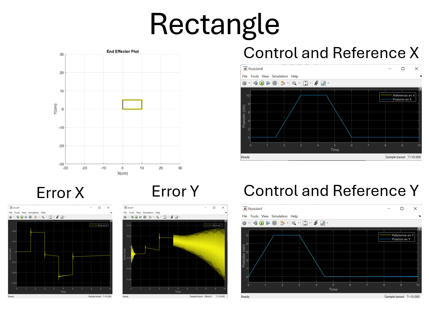
Rectangle
- Generated a 10 s reference with a signal generator to draw a 10x5 cm rectangle starting at (0 cm, 0 cm).
- X reference: trapezoidal pulse with 0 cm until 1.5 s, rising lineally from 0 cm to 10 cm between 1.5 s and 3 s, constant at 10 cm between 3 s and 4.5 s, falling lineally from 10 cm to 0 cm between 4.5 s and 6 s, constant at 0 cm from 6 s to the end at 10 s.
- Y reference: trapezoidal pulse rising lineally from 0 cm to 5 cm between 0 s and 1.5 s, constant at 5 cm between 1.5 s and 3 s, falling lineally from 5 cm to 0 cm between 3 s and 4.5 s, constant at 0 cm from 4.5 s to the end at 10 s.
- Designed a PID controller with reference, feedback and output signals. Parameters: $Kp=3$, $Kd=85$, $Ki=1$.
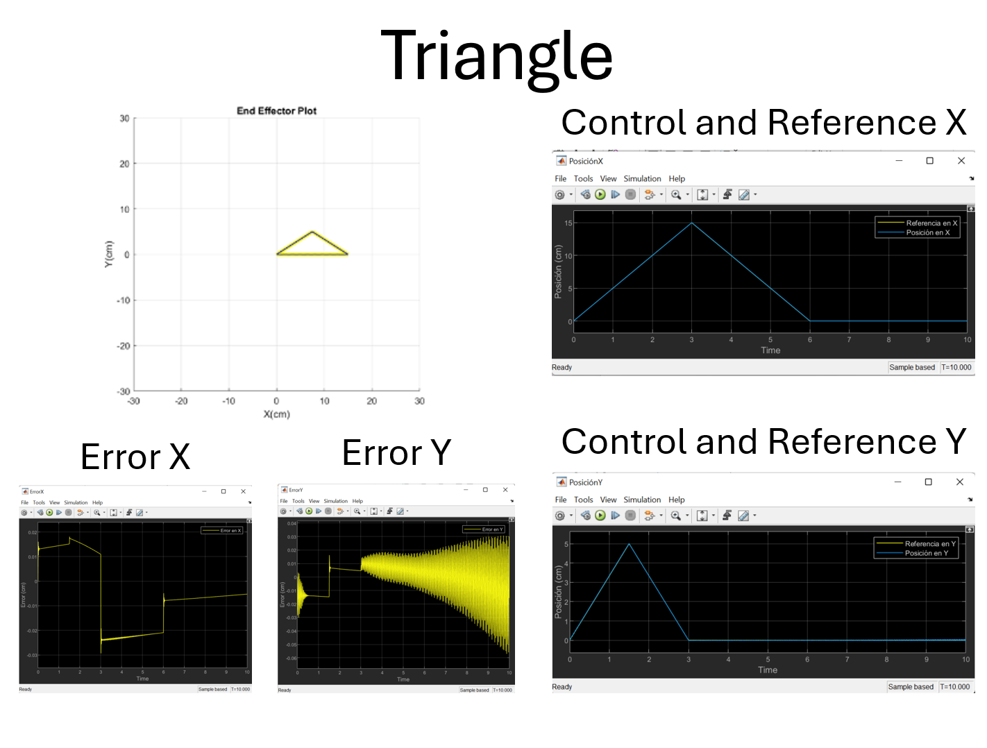
Triangle
- Generated a 10 s reference with a signal generator to draw a triangle with vertices at (0 cm, 0 cm), (7.5 cm, 5 cm), (15 cm, 0 cm).
- X reference: triangular pulse rising lineally from 0 cm to 15 cm between 0 s and 3 s, falling lineally from 15 cm to 0 cm between 3 s and 6 s, constant at 0 cm from 6 s to the end at 10 s.
- Y reference: triangular pulse rising lineally from 0 cm to 5 cm between 0 s and 1.5 s, falling lineally from 5 cm to 0 cm between 1.5 s and 3 s, constant at 0 cm from 3 s to the end at 10 s.
- Designed a PID controller with reference, feedback and output signals. Parameters: $Kp=3$, $Kd=85$, $Ki=1$.
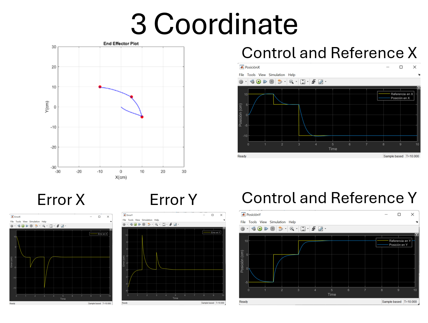
3 Coordinates
- Generated a 10 s reference signal with combinations of Heaviside step functions to reach user-defined coordinate:
- X reference: Heaviside step function with amplitude from first coordinate from 0 s to 1.5 s, with amplitude from second coordinate from 1.5 s to 3 s, with amplitude from third coordinate from 3 s to the end at 10 s.
- Y reference: Heaviside step function with amplitude from first coordinate from 0 s to 1.5 s, with amplitude from second coordinate from 1.5 s to 3 s, with amplitude from third coordinate from 3 s to the end at 10 s.
- Designed a PD controller with reference, feedback and output signals. Parameters: $Kp=8$, $Kd=3$.
Forces
- Converted our output control forces from cartesian logic to polar axes.
- Left motor: $-Control_x+Control_y$.
- Right motor: $-Control_x-Control_y$.
Video
Gallery